В этом уроке рассмотрим, как подключить несколько датчиков Atlas к одному последовательному порту Arduino.
Проект
В этом уроке мы будем расширять один последовательный порт Arduino UNO UART (Rx/Tx) так, чтобы можно было подключить несколько датчиков Atlas. Расширение осуществляется с помощью платы расширения последовательного порта 8:1 (англ. название - 8:1 Serial Port Expander). Порт Arduino подключается к "расширителю", после чего сигнал направляется на восемь портов, к которым подключены периферийные устройства. Для простоты мы будем использовать три порта, но с помощью нескольких дополнительных шагов вы можете сделать расширение, чтобы использовать все восемь.
Связь осуществляется через режим UART, а результаты отображаются на последовательном мониторе Arduino. По умолчанию показания подключенных датчиков опрашиваются непрерывно. Затем можно открыть отдельные каналы, что позволит пользователю общаться с определенным датчиком. Преимущества такого подхода:
- Разворачивание одного последовательного порта UART (Rx/Tx) на восемь дополнительных портов.
- Легко следить за тем, какой канал открывается с помощью встроенных светодиодов на модуле расширения.
- Работает со следующими датчиками Atlas EZO: pH, соленость, растворенный кислород (DO), температура, окислительно-восстановительный потенциал (ORP), диоксид углерода (CO2), перистальтический насос.
- Выходной сигнал датчика в реальном времени и взаимодействие с пользователем.
Комплектующие
Компоненты оборудования, которые нам будут нужны в этом уроке:
- Arduino UNO × 1
- Плата расширения × 1
- Макет (универсальный) × 1
- Датчик растворенного кислорода × 1
- Датчик солености × 1
- Датчик pH × 1
- Перемычки × 1
Программные приложения:
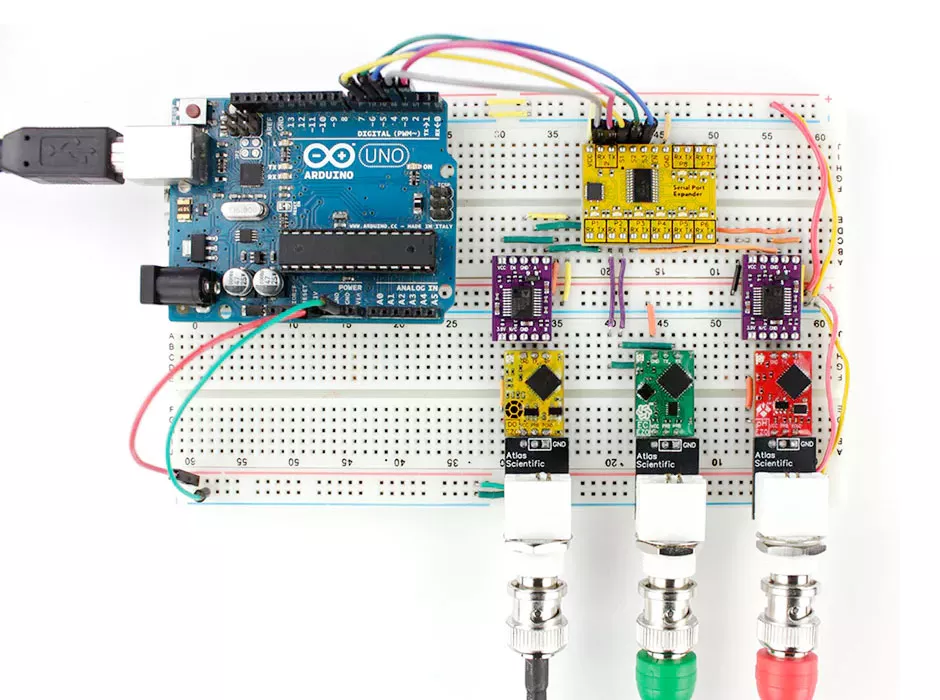
Схема соединения
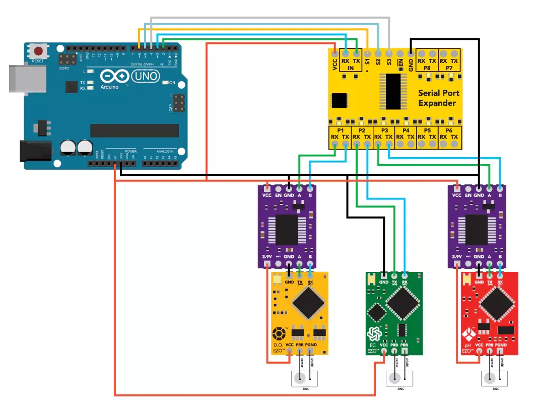
Соберите все комплектующие согласно схеме выше. Убедитесь, что датчики находятся в режиме UART, прежде чем подключать их к расширителю. Чувствительность датчиков - это то, что дает им высокую точность. Но это также означает, что они подвержены помехам от другой электроники и необходима электрическая изоляция. Изоляторы напряжения используются для изоляции датчиков растворенного кислорода и pH от датчика солености. Без изоляторов показания ошибочны.
Программа Arduino
В коде этого руководства используется настраиваемая библиотека и файл для цепей EZO в режиме UART. Вам нужно будет добавить их в вашу Arduino IDE, чтобы использовать код. Следующие шаги включают процесс добавления дополнения в IDE.
- Загрузите Ezo_uart_lib, zip-папку с GitHub на свой компьютер.
- На вашем компьютере откройте IDE Arduino (вы можете скачать IDE здесь, если она у вас еще не установлена).
- В IDE перейдите в:
# Sketch -> Включить библиотеку -> Добавить ZIP-библиотеку (Sketch -> Include Library -> Add.ZIP Library)
Выберите папку Ezo_uart_lib, которую вы только что загрузили. Соответствующие файлы теперь включены. - Скопируйте код из Serial_port_expander_example на рабочую панель IDE. Вы также можете получить к нему доступ из папки Ezo_uart_lib, загруженной выше.
- Скомпилируйте и загрузите код Serial_port_expander_example в Arduino Uno.
- Последовательный монитор используется в качестве канала связи. Чтобы открыть последовательный монитор, перейдите в:
# Инструменты -> Последовательный монитор (Tools -> Serial Monitor)
или нажмите Ctrl + Shift + M на клавиатуре. Установите скорость передачи 9600 и выберите «Возврат каретки» (англ - carriage return). Показания датчика теперь должны постоянно отображаться и пользователь сможет взаимодействовать с отдельными датчиками.
//This code works similarly to the serial port expander sample code in terms of the interface
//but constantly polls all the circuits by default
//To open a channel (marked on the board as P1 to P8) send the number of the channel followed by a colon and the command (if any) that you want to send. End the string with a carriage return.
//1:r<CR>
//2:i<CR>
//3:c<CR>
//4:r<CR>
//To open a channel and not send a command just send the channel number followed by a colon.
//1:<CR>
//3:<CR>
#include <Ezo_uart.h>
#include <SoftwareSerial.h> //we have to include the SoftwareSerial library, or else we can't use it
#define rx 2 //define what pin rx is going to be
#define tx 3 //define what pin tx is going to be
SoftwareSerial myserial(rx, tx); //define how the soft serial port is going to work
int s1 = 6; //Arduino pin 6 to control pin S1
int s2 = 5; //Arduino pin 5 to control pin S2
int s3 = 4; //Arduino pin 4 to control pin S3
int port = 1; //what port to open
const uint8_t bufferlen = 32; //total buffer size for the response_data array
char response_data[bufferlen]; //character array to hold the response data from modules
String inputstring = ""; //a string to hold incoming data from the PC
// create objects to represent the Modules you're connecting to
// they can accept hardware or software serial ports, and a name of your choice
Ezo_uart Module1(myserial, "DO");
Ezo_uart Module2(myserial, "EC");
Ezo_uart Module3(myserial, "PH");
// the modules are ordered in an array according to their position in the serial port expander
// so Modules[0] holds the module in port1, Modules[1] holds the module in port 2, etc
const uint8_t module_count = 3; //total size fo the Modules array
Ezo_uart Modules[module_count] = { //create an array to hold all the modules
Module1, Module2, Module3
};
void setup() {
Serial.begin(9600); //Set the hardware serial port to 9600
myserial.begin(9600); //set baud rate for the software serial port to 9600
inputstring.reserve(20); //set aside some bytes for receiving data from the PC
pinMode(s1, OUTPUT); //Set the digital pin as output
pinMode(s2, OUTPUT); //Set the digital pin as output
pinMode(s3, OUTPUT); //Set the digital pin as output
// in order to use multiple circuits more effectively we need to turn off continuous mode and the *ok response
for (uint8_t i = 0; i < module_count; i++) { // loop through the modules
open_port(i + 1); // open the port
Modules[i].send_cmd_no_resp("c,0"); //send the command to turn off continuous mode
//in this case we arent concerned about waiting for the reply
delay(100);
Modules[i].send_cmd_no_resp("*ok,0"); //send the command to turn off the *ok response
//in this case we wont get a reply since its been turned off
delay(100);
Modules[i].flush_rx_buffer(); //clear all the characters that we received from the responses of the above commands
}
}
void loop() {
if (Serial.available() > 0) { //if we get data from the computer
inputstring = Serial.readStringUntil(13); //receive it until the carraige return delimiter
port = parse_input(inputstring); //parse the data to either switch ports or send it to the circuit
open_port(port); //set the port according to the data we sent
if (inputstring != "") { //if we have a command for the modules
Modules[port - 1].send_cmd(inputstring, response_data, bufferlen); // send it to the module of the port we opened
Serial.print(port); //print the modules port
Serial.print("-");
Serial.print(Modules[port - 1].get_name()); //print the modules name
Serial.print(": ");
Serial.println(response_data); //print the modules response
response_data[0] = 0; //clear the modules response
}
else {
Serial.print("Port is set to "); //if were not sending a command, print the port
Serial.println(port);
}
}
for (uint8_t i = 0; i < module_count; i++) { //loop through the modules and take a reading
open_port(i + 1);
print_reading(Modules[i]);
Serial.print(" ");
}
Serial.println();
}
void print_reading(Ezo_uart &Module) { //takes a reference to a Module
//send_read() sends the read command to the module then converts the
//answer to a float which can be retrieved with get_reading()
//it returns a bool indicating if the reading was obtained successfully
if (Module.send_read()) {
Serial.print(Module.get_name()); //prints the module's name
Serial.print(": ");
Serial.print(Module.get_reading()); //prints the reading we obtained
Serial.print(" ");
}
}
uint8_t parse_input(String &inputstring) { //this function will decode the string (example 4:cal,1413)
int colon = inputstring.indexOf(':'); //find the location of the colon in the string
if ( colon > 0) { //if we found a colon
String port_as_string = inputstring.substring(0, colon); //extract the port number from the string and store it here
inputstring = inputstring.substring(colon + 1); //extract the message from the string and store it here
return port_as_string.toInt(); //convert the port number from a string to an int
}
else { //if theres no colon
return port; //return the current port and dont modify the input string
}
}
void open_port(uint8_t _port) { //this function controls what port is opened on the serial port expander
if (port < 1 || module_count > 8)_port = 1; //if the value of the port is within range (1-8) then open that port. If it’s not in range set it to port 1
uint8_t port_bits = _port - 1;
digitalWrite(s1, bitRead(port_bits, 0)); //Here we have two commands combined into one.
digitalWrite(s2, bitRead(port_bits, 1)); //The digitalWrite command sets a pin to 1/0 (high or low)
digitalWrite(s3, bitRead(port_bits, 2)); //The bitRead command tells us what the bit value is for a specific bit location of a number
delay(2); //this is needed to make sure the channel switching event has completed
}
Чтобы открыть канал, обозначенный P1-P8 на плате расширителя, отправьте номер канала с двоеточием и команду. Завершите строку возвратом каретки (клавиша ENTER на клавиатуре). Например, 3:i откроет третий канал и запросит информацию об устройстве.
Чтобы открыть канал и не отправлять команду, просто введите номер канала и двоеточие. Завершите строку возвратом каретки (клавиша ENTER на клавиатуре). Например, 2: откроет второй канал. Теперь вы можете отправлять любые команды, специфичные для этого датчика, такие как cal, ? который сообщит информацию о калибровке. Обратитесь к спецификациям датчиков для получения списка команд.
Мы использовали только три из восьми портов. Чтобы использовать больше портов, следуйте схеме подключения, показанной на шаге 1, и перейдите к портам 4, 5 и т.д. При необходимости используйте изоляторы. Пример кода, Serial_port_expander_example, также нуждается в некоторой модификации. Смотрите комментарии в коде для руководства.